Making a Gate Smart

For this project I will (hopefully) use information from this post: Building a Smart Home - Part 7 Motorised Gate by Aaron Powell
Aaron has a Shelly1 v3 and a BFT Deimos BT A 400, whereas I have a Shelly Plus 1PM and a BFT HQSC-D Deimos BT aftermarket replacement board, made to replace the "Deimos BT UL", but it isn't clear to me which product that actually is - best guess here.
The Shelly Plus 1PM has power measurement capability that I will not be using here, I bought it because it was in stock and the Shelly1 was not. The Plus variety also has overcurrent and overvoltage protections, bluetooth, and uses an ESP32 for comms rather than an ESP8266. A Shelly1 would have been fine for this project. The gate board was replaced with an aftermarket part for the same reason of availability.
Author's note: the PM variant of the board was not capable of providing the solution I needed, and I bought a Shelly Plus 1.


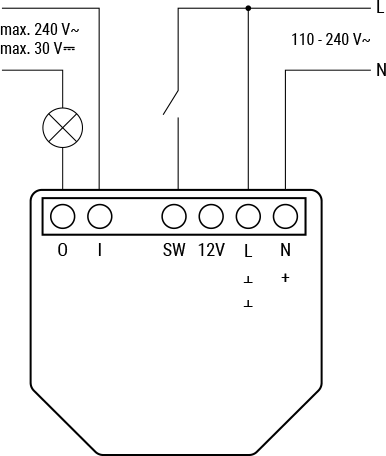
Left/red: Shelly Plus 1PM. Right/blue: Shelly Plus 1
I'll start by understanding Aaron's solution, then modifying it to fit my hardware.
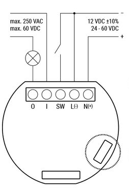
Aaron connected L to L (for DC that's ground) and N to N (positive for DC), O to 61 (START) and I to 60 (COM). Wires to I and L are red, N is black and O is white. I'm not going to assume those colours are reliable indicators of much because Aaron does not address it. I'm also not particularly well versed with EEE, this project being at the edge of my knowledge.
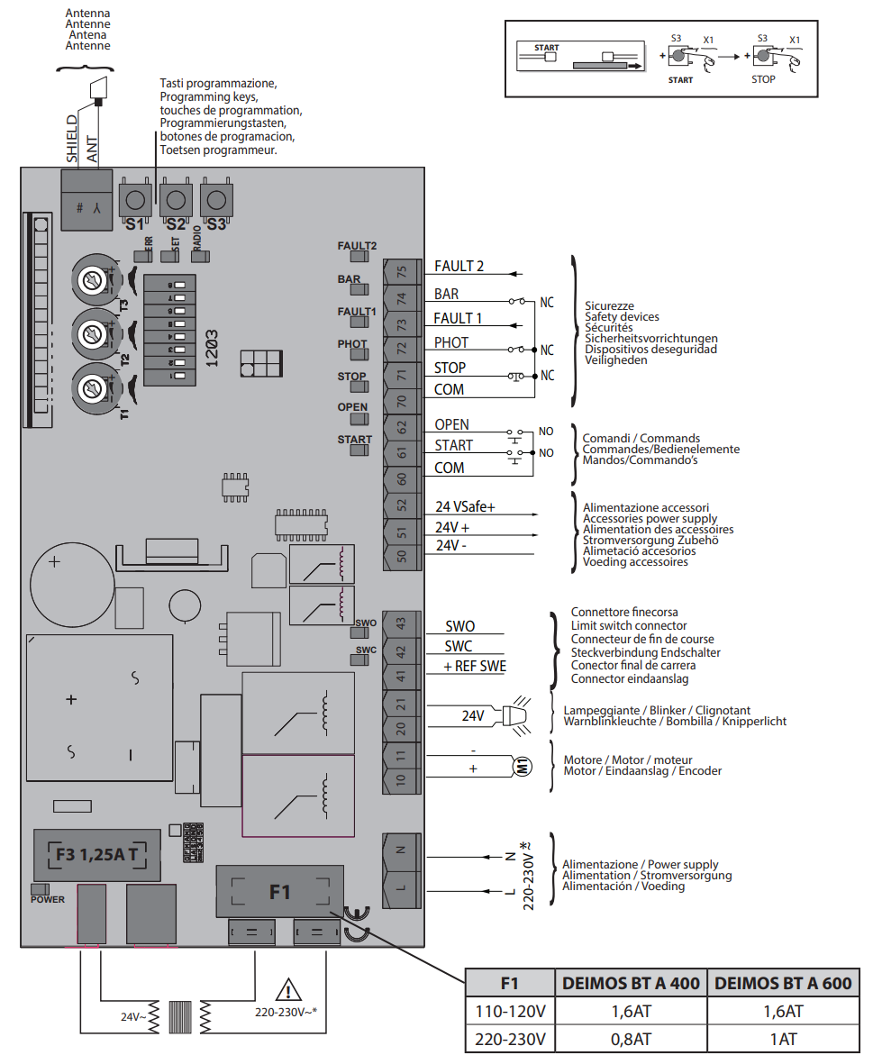
Aaron's hardware: Shelly1 and Deimos BT A400
Here are the same diagrams for my hardware:
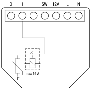
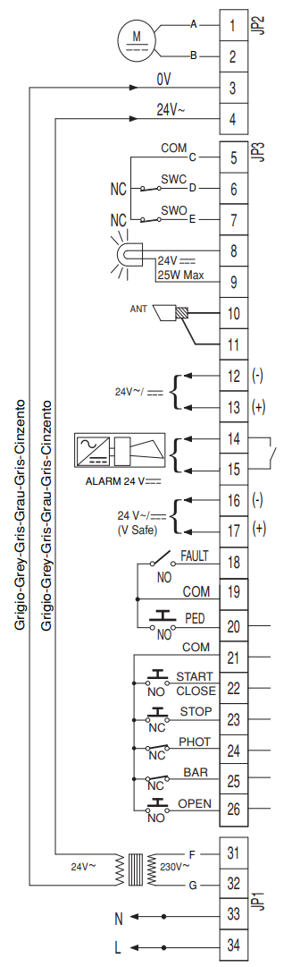
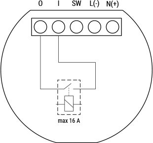
My hardware: Shelly Plus 1 and Deimos BT UL025
The Shelly device closes the circuit between I and O when told to, which can be used to close a circuit on the board to trigger the open/close sequence.
This particular gate is configured with a keypad and also an RF board for remotes. A sub-board controls the inputs from those and handles authentication, but ultimately it simply closes a circuit once authentication is confirmed. All I need to do is piggy back the Shelly onto this circuit in parallel.

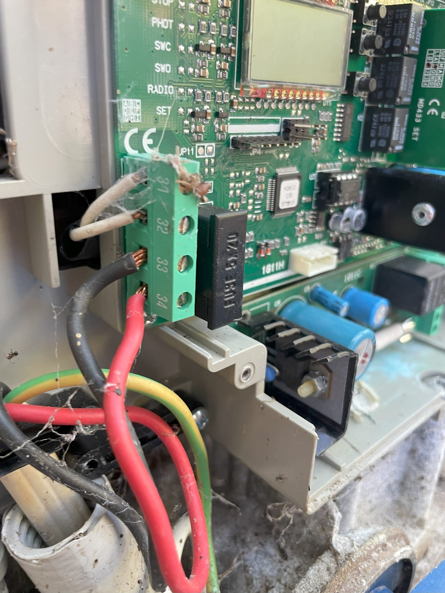
Board photos
The bottom left corner contains 31-34. Red wire to 34 and black to 33, with two grey wires coming out of 31/32. The manual says 33/34 is "single-phase power supply 120VAC, 60Hz" with 31/32 labelled "transformer primary circuit 120VAC". However, measuring the voltage 33/34 shows 240V. It's definitely mains power.
Joining 21 and 22 momentarily with a multimeter causes the gate to open or close, although not with the same behaviour as when the remote is used. The remote either stops motion or starts motion in the opposite direction to the previous direction of motion, but what I observed here was that a closed gate begins to open, gets paused, then continues to open rather than beginning to close. Once the gate is fully open, another signal will begin to shut it.
My first successful configuration used the 240VAC from 34/34 to power the Shelly Plus 1 (into L/N) and then used breadboard wires to connect I/O on the Shelly to 21/22 on the main board, which also gets input from... somewhere else, maybe the road-side keypad. The Shelly can be told to close the switch, and the gate does things. Simple and easy, but not very versatile.
The next level of user experience was to integrate it into HomeAssistant via the Shelly integration. It works, but doesn't feed back any information about the position of the gate. You can send the signal whenever you like, but unless you are watching a camera feed, you can't be sure what is happening. So I set up a camera. I run Frigate already so that was fairly simple.
Having to open HomeAssistant and navigate to the Gate page is good, but there are a few things that are even better: widgets, and CarPlay.
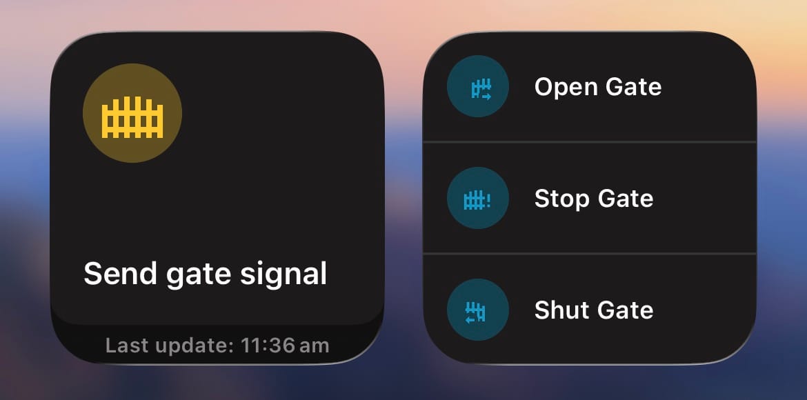
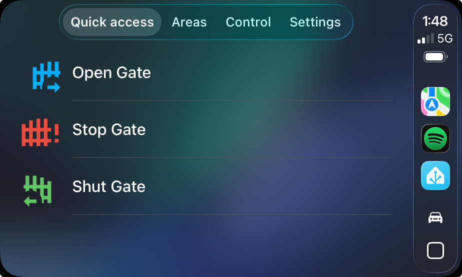
Widgets make the experience as seamless as using a traditional gate remote
How does HomeAssistant know whether to do anything when the user activates the Shut Gate button? We must keep track of the position of the gate virtually with an estimate. I chose to keep a simple number, percentage of openness.
When the gate it shut, the user can activate the Open Gate script. That begins an automation that ticks the openness upward, firstly at speed, and for the final foot or so it moves slowly, as the gate creeps slowly to the end-stop.
The user can use Stop Gate at any time when the openness is not 0% or 100%, and send a signal to the gate which will halt movement, provided the gate is actually moving at that time - if you get the synchronisation wrong, and the gate has already stopped, it will begin moving again. We can mitigate this with a deasdzone
Shut Gate functions the same as Open Gate, but only triggers when the openness is 100%. Naturally there is a script in the background with a name like Gate Action and the Open Gate script just checks whether openness is 0% before calling Gate Action.
This all works fairly well! Multiple users can share the virtual gate controller without hassle. The CarPlay integration is fantastic, allowing the driver to operate the gate without touching their phone or rummaging around for a physical remote control. However, it does leave some to be desired.
Firstly, the virtual system does not play nice with any interactions it didn't initiate. Opened the gate with the keypad? Synchronisation is lost, until you close it with the keypad - if you do that. Same with using the remote controllers. I mitigate this with a slider in HomeAssistant that the user can set the openness with, and a dropdown to specify what will result from the next gate action. These were required in the background anyway, but exposing them was unfortunately necessary.
I have reached the limits of functionality using just a Shelly Plus 1. I'm building a replacement using an ESP32 that will solve many of these issues. Stay tuned!